Skip to content


Please Refer to The Installation Wiring Diagrams Below
Download the Easy-to-Follow Installation Manual
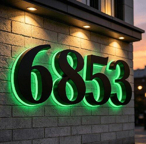
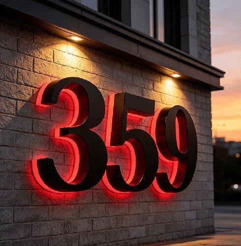
⚠️ CRITICAL: RGB Wiring & Connection Notice — Read Before Installing
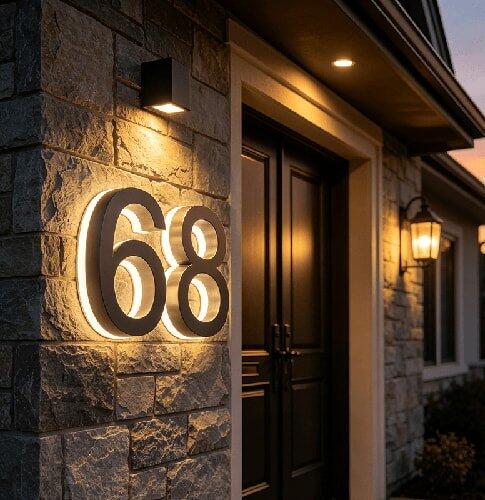
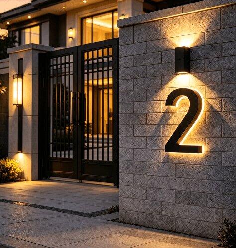
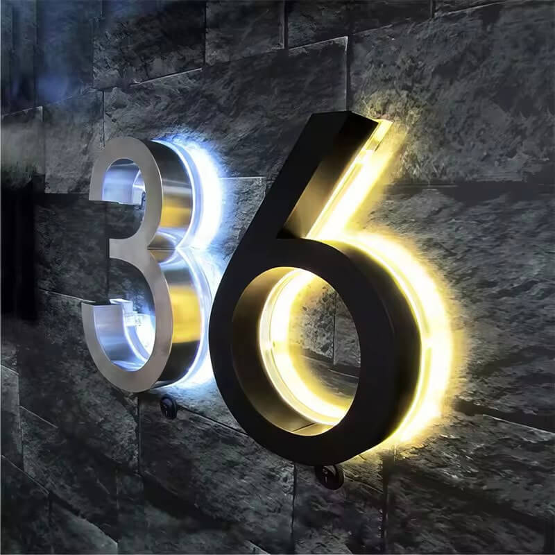
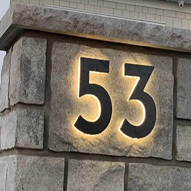
Watch How to Install Our Stunning Illuminated House Number Signs
Watch Our Guide to Installing Lighted Business Signs


Please follow these guidelines carefully to ensure safety and proper functionality
Key Points to Remember:
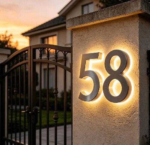
1. The illuminated letters sign / lighted house numbers operate on 12V DC power.
2. The illuminated signage cannot be directly connected to an AC power source.
3. To power the personalized lighted signs, you’ll need an LED Driver that converts 110V AC to 12V DC.
4. Make sure to connect the backlit signage / front lit signs to the correct output side of the LED Driver.
5. Afterward, connect the LED Driver to your 110V AC power source.
Important Safety Notes:
- Never connect the led illuminated signage directly to an AC power source (e.g., a 110V-240V AC panel or outlet). Doing so is extremely dangerous and can cause serious harm or damage.
- Always use a 110V to 12V AC-to-DC converter (LED Driver) for this purpose.
Installation Reminder:
For your safety and compliance with regulations, all wiring and installation should be carried out by a certified electrician. It’s essential to follow the correct connection diagrams, ratings, safety regulations, and electrical codes.